
Electrical Wiring II
- Jun 21, 2023
- 7 min read

Table of Contents
About this module
This module provides an overview of:
Wiring Methods:
Definition of Wiring Methods, Types of Wiring Methods, Installation Techniques
Types of Electrical Connections:
Types of Electrical Connections, Proper Connection Techniques, Safety Considerations
Specialized Wiring for Specific Equipment or Systems:
Examples of Specialized Wiring, Requirements for Specialized Wiring, Techniques for Installation
Code of Practice for Electrical Installation:
Overview of the Electrical Code, Importance of Following the Electrical Code, Key Requirements of the Electrical Code
Wiring Diagrams and Schematics:
Overview of Wiring Diagrams and Schematics, Types of Wiring Diagrams and Schematics, Symbols Used in Wiring Diagrams and Schematics
Types of Circuits:
Definition of Circuits, Types of Circuits (Series, Parallel, Combination), How Circuits Work
Troubleshooting:
Definition of Troubleshooting, Types of Troubleshooting for Common Electrical Problems (Short Circuits, Open Circuits, Ground Faults), Techniques for Troubleshooting
Types of Tests to be Conducted for Troubleshooting:
Overview of Electrical Testing, Types of Electrical Tests (Continuity Testing, Voltage Testing, Resistance Testing), Proper Techniques for Conducting Electrical Tests
Wiring Methods
Different types of electrical connections
There are several types of electrical connections used in electrical systems, including:
Soldered Connections - In this type of connection, a metal alloy called solder is melted and used to join two wires or electrical components.
Crimped Connections - This involves using a special tool to crimp a metal connector onto a wire, creating a secure connection.
Screw Connections - This involves connecting wires to a terminal or other electrical component using screws to secure the connection.
Push-In Connections - This involves pushing the stripped end of a wire into a terminal block or other electrical component and securing it in place.
Welded Connections - This involves welding two metal parts together to create a permanent connection.
Twist-On Connections - This involves twisting two or more wires together and securing them with a wire connector, also known as a wire nut.
Terminal Block Connections - This involves using a terminal block, which is a type of electrical connector that allows multiple wires to be connected to a single point.
The type of connection used depends on the specific application and the electrical system being used.
Wiring methods and techniques
Wiring methods and techniques are used to safely and efficiently connect electrical devices and equipment to a power source.
Some common wiring methods and techniques include:
Conduit wiring: This method involves running wires through metal or plastic pipes called conduits. This provides protection to the wires from physical damage and exposure to moisture.
Cable wiring: This involves running wires inside flexible or rigid metal or plastic sheaths, called cables. Cables can be used in various wiring configurations, including armored cable (AC) and non-metallic sheathed cable (NM).
Busbar wiring: Busbars are flat metal bars that carry electrical current. They are used to distribute power throughout a building and can be mounted on insulators or encased in a protective housing.
Surface wiring: Surface wiring involves running wires along the surface of walls or ceilings using conduit or raceways.
Point-to-point wiring: This involves connecting devices directly to each other using individual wires, making it easy to replace or modify connections.
Terminal block wiring: Terminal blocks are used to connect multiple wires together. They are typically mounted on a panel or a DIN rail and provide a convenient way to organize and connect wires.
Printed circuit board (PCB) wiring: This involves connecting components on a printed circuit board using conductive traces. PCBs are used extensively in electronics and provide a compact and efficient way to wire complex circuits.
Proper wiring methods and techniques are critical to ensuring electrical safety and avoiding hazards such as electrical shock, fires, and equipment damage. It is important to follow applicable codes and regulations when wiring electrical systems, and to use appropriate wiring materials and methods for the specific application.
Specialised wiring for specific equipment or systems
Specialized wiring refers to the specific types of wiring used for particular equipment or systems, such as:
Control wiring: Used for the control of electrical systems, typically low voltage wiring that connects control devices such as switches, relays, and sensors to control panels.
Instrumentation wiring: Used to connect instruments and sensors to control systems.
Audio/visual wiring: Used for audio and video systems, including home theaters, speakers, and soundbars.
Data cabling: Used for data networks, including ethernet, fiber optic, and coaxial cables.
Security system wiring: Used for security cameras, alarms, and access control systems.
Fire alarm wiring: Used for fire alarm systems, including smoke detectors, pull stations, and strobe lights.
HVAC wiring: Used for heating, ventilation, and air conditioning systems, including thermostats, air handlers, and compressors.
Motor control wiring: Used for the control of motors, typically high voltage wiring that connects motor starters, contactors, and overloads to the motor.
Solar panel wiring: Used for connecting solar panels to inverters and batteries.
Code of Practice for Electrical Installation
Based on SS 638: 2018 Code of Practice for Electrical Installation
It provides guidelines for the design, installation, and maintenance of electrical systems in buildings, including the selection of equipment and materials, installation methods, and testing procedures.
The code covers a wide range of electrical installations, including power distribution, lighting, earthing, lightning protection, and emergency power supply systems. It aims to ensure electrical safety and reliability while promoting energy efficiency and sustainability in building electrical systems.
From 1 March 2009 onwards, all new electrical installations, including addition and alteration to existing electrical installations, may use new colour cables of brown, black, grey (for line), blue (for neutral) and green-and-yellow (for earth) as set out in the amended SS CP 5:1998.
A transition period of 24 months from 1 March 2009 to 28 February 2011 is given before the new cable colour becomes mandatory on 1 March 2011. During the transition period, either the old or new cable colour code, but not both, may be used. Starting from 1 March 2011, the new cable colour shall be used in all new electrical installations, as well as addition and alteration to existing electrical installations.

Based on the New Wire Colour
The 3 types of electrical wires – Brown, Blue and Green with Yellow – serve different purposes.
The Brown wire is the Live wire which carries the electricity from the source to the electrical appliances.
The Blue wire is the Neutral wire which carries the electricity back to the source. Mixing up Neutral and Live wire can lead to serious consequences.
The Green with Yellow wire which is the Earth wire provides a path back to the source when there is an electrical fault to prevent the possibility of electrocuting a person.
Wiring Diagrams and Schematics
Understanding electrical diagrams and schematics
Electrical diagrams and schematics are graphical representations of electrical circuits and systems. They use symbols and diagrams to show the connections between different components, including switches, resistors, capacitors, and transformers, as well as the flow of electricity through the circuit.
There are several types of electrical diagrams and schematics, including:
Block diagrams: These diagrams provide an overview of the entire system or circuit, showing major components and connections between them.
Wiring diagrams: These diagrams show the physical layout of the electrical system, including the wiring connections between components and devices.
Schematic diagrams: These diagrams show the functional relationships between components in the circuit, but do not include physical details or layout.
Pictorial diagrams: These diagrams show the physical layout of the system or circuit, but use realistic images of components rather than schematic symbols.
Circuit diagrams: These diagrams show the connections and components within a specific circuit or system, including the power source, switches, resistors, and other devices.
To understand an electrical diagram or schematic, it is important to understand the symbols used, as well as the conventions for representing different types of components and connections. Reading and interpreting electrical diagrams is an important skill for electrical engineers, electricians, and other professionals who work with electrical systems.
Types of circuits
 | Series Circuits
|
 | Parallel Circuits
|
Phases
 | 1 (Single) Phase
|
 | 2 (Dual/ Split) Phase
|
 | 3 (Three) Phase
|
Distribution Boards
 | Distribution Board (DB)
|
Troubleshooting of common electrical wiring problems and diagnosing faults
Common electrical wiring problems include issues with switches, outlets, and light fixtures not functioning properly, tripping circuit breakers or blowing fuses, and electrical shock or fire hazards caused by faulty wiring.
To diagnose faults in electrical wiring, it is important to follow safe working procedures and use appropriate tools such as multimeters, circuit testers, and voltage detectors.
The following steps can be taken:
Identify the problem: Understand what the specific issue is by observing the symptoms and identifying the affected circuits or components.
Check power supply: Ensure that the power supply is on and that there is no disruption in the flow of electricity.
Check circuit breakers and fuses: Check for tripped circuit breakers or blown fuses, and replace them as necessary. Link: Appliance Circuit Basics | Repair and Replace Link: What are Open Circuits? | Repair and Replace Link: What is a Short Circuit? | Repair and Replace
Check wiring connections: Check wiring connections for loose or disconnected wires, corrosion, and damage.
Check electrical devices: Test electrical devices such as switches, outlets, and light fixtures to see if they are functioning properly.
Use diagnostic tools: Use diagnostic tools such as multimeters and circuit testers to test voltage, continuity, and resistance.
Repair or replace faulty components: Repair or replace faulty components such as damaged wires, switches, outlets, or light fixtures.
Test system: Test the system again to ensure that the issue has been resolved and that the system is functioning properly.
It is important to note that electrical wiring should only be performed by a licensed electrician to ensure safety and compliance with electrical codes and regulations.
Types of Tests for Troubleshooting
Continuity Test: This test is used to check if there is a complete electrical connection between two points. A beep sound confirms that there is continuity, while no sound indicates there is a break in the connection. Link: How to do a Continuity Test With a Multimeter | Repair and Replace
Voltage Test: This test measures the voltage between two points in a circuit. It is used to check the presence or absence of voltage or to verify the voltage levels. Link: How to Test Voltage in a Receptacle | Repair and Replace
Current Test: This test measures the flow of electric current through a circuit. It is used to check the current flowing in a circuit or to verify the current levels.
Resistance Test: This test measures the resistance of an electrical component. It is used to check the health of a resistor or to verify the resistance levels. Link: Megger Testing Procedure
Components Troubleshooting using a Multimeter
 | Cable and Wires
(https://www.electricaltechnology.org/2014/01/testing-electrical-and-electronics-components-with-multimeter.html) |
 | Switch/ Push Buttons
|
 | Fuse
|
 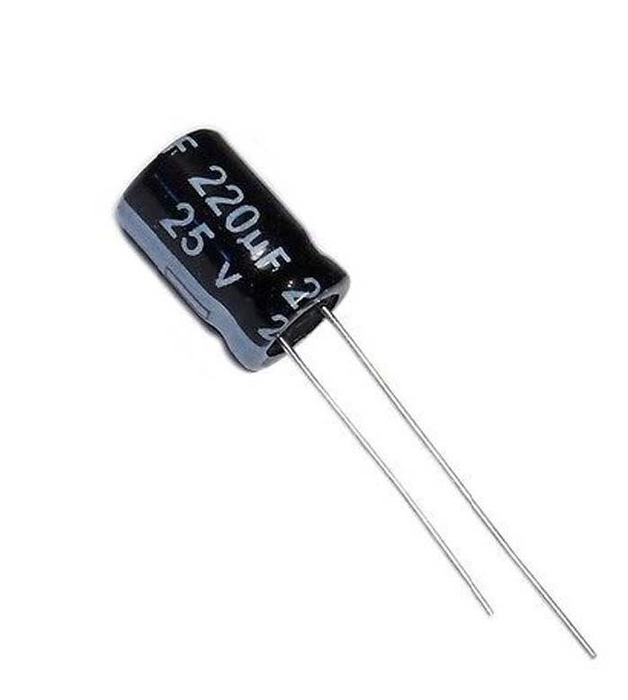 | Capacitor
(https://www.electricaltechnology.org/2013/06/how-to-check-capacitor-with-digital.html) |
 | Diode & LED
(https://www.electricaltechnology.org/2018/06/how-to-test-a-diode-using-digital-analog-multimeter.html)) |
 | Transistor
|
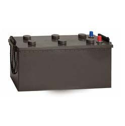 | Battery (https://www.electricaltechnology.org/2014/08/how-to-test-a-battery-with-test-meter.html) |
 | Resistor/ Burnt Resistors
|